
Aka cheap LED driver
Traditional way of connecting 4 digits x 7segment display to microprocessor suggest using 4 transistors and 12 resistors:
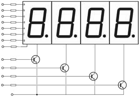
Would You be interested in shrinking everything down to LED display and 4 resistors ONLY ?
Then continue reading.
Assuming one LED segment (digit’s stick) drives 20mA current this setup can take up to 160mA of power (7segments+dot)*20 if we will use multiplexing (turning just one digit at a time, then next, then next,… an doing it very very fast). Even this trick takes too much power for portable devices running on batteries.
Now I’will try to illustrate traditional multiplexing vs. proposed kinda charlieplexing:
In multiplexing each digit lights-on then turns-off, then next lights-on, and so on:
In charlieplexing each segment of digit lights-on then turns-off, then next lights-on, and so on:

As You see this way we never exceed 20mA – because at every moment only one segment is active. This reduces power consumption and eliminates need of transistors – maximum current limit of digital pins Arduino boards – 40mA.
Plain 4×7 LED modules

They come in two flavours – common cathode(upper diagram) and common anode(lower diagram):
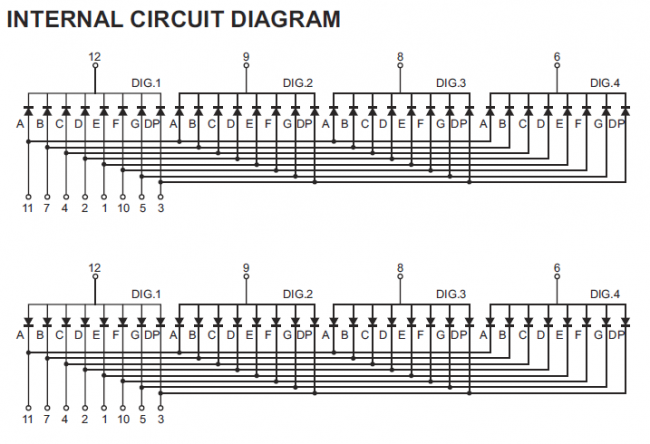
Pinout diagram:

As You see, it is enough to put a resistor on each digit common pin (12, 9, 8 or 6) and we have limited current to desired value. I used 5V logic and 220ohm resistors, I = U/R = 5/220 = 23mA.
First prototype was mini breadboard on top of Arduino UNO:
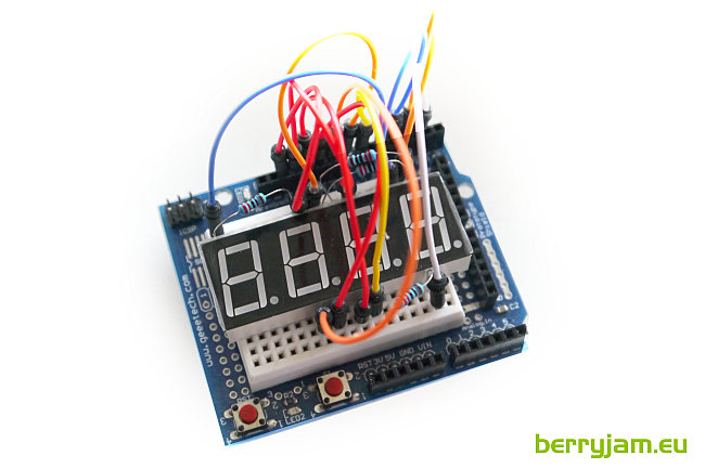
The schematic:

Next thing is code
// 4x7 LED driver firmware v0.1
// Ignas Gramba
// www.berryjam.eu
//
byte anode[4]  =  {5,     4,      3,      2};
                // Digit, Digit2, Digit3, Digit4

byte cathode[7] = { 12, 11, 10, 9, 8, 7, 6};
                //  A,  B,  C,  D, E, F, G


byte four_digits[4][4] = {
  {1, 0, 0, 0}, // First  digit is on
  {0, 1, 0, 0}, // Second digit is on
  {0, 0, 1, 0}, // Third  digit is on
  {0, 0, 0, 1}  // Fourth digit is on
};

byte seven_segments[14][7] = {
  { 0,0,0,0,0,0,1 },  // = 0
  { 1,0,0,1,1,1,1 },  // = 1
  { 0,0,1,0,0,1,0 },  // = 2
  { 0,0,0,0,1,1,0 },  // = 3
  { 1,0,0,1,1,0,0 },  // = 4
  { 0,1,0,0,1,0,0 },  // = 5
  { 0,1,0,0,0,0,0 },  // = 6
  { 0,0,0,1,1,1,1 },  // = 7
  { 0,0,0,0,0,0,0 },  // = 8
  { 0,0,0,0,1,0,0 },  // = 9
  { 1,1,1,1,1,1,1 },  // = 10 (OFF)
  { 1,1,1,1,1,1,0 },  // = 11 ("-")
  { 0,1,1,0,0,0,0 },  // = 12 ("E")
  { 1,1,1,1,0,1,0 }   // = 13 ("r")
};

int distance = 0;

void setup(){

  for (byte a = 0; a < 4; ++a) {
    pinMode (anode[a], OUTPUT);
  }
  for (byte b = 0; b < 7; ++b) {
    pinMode (cathode[b], OUTPUT);
  }

}

void loop(){

  LED_WriteNumber(distance);

}

void LED_WriteDigit(byte digit, byte value) {
    for (byte digCount = 0; digCount < 4; ++digCount) {
      digitalWrite(anode[digCount], four_digits[digit-1][digCount]);
    }

    for (byte segCount = 0; segCount < 7; ++segCount) {
      digitalWrite(cathode[segCount], seven_segments[value][segCount]);
      delayMicroseconds(100);
      digitalWrite(cathode[segCount], 1);
    }
}

void LED_WriteNumber(int number) {
    int  ones, tens, hundreds;

    ones = (number%10);
    tens = ((number/10)%10);
    hundreds = ((number/100)%10);

    if (hundreds == 0) hundreds = 10;
    if ((tens ==0)&&(hundreds ==0)) tens = 10;

    LED_WriteDigit(1, hundreds);
    LED_WriteDigit(2, 10);
    LED_WriteDigit(3, tens);
    LED_WriteDigit(4, ones);
}
This code was written for common anode version, if You have common cathode just swap “0” and “1” in program code. I intentionally separated first digit (meters) from centimeters, so my second digit in this program is always off (digit value = 10). Everything else is pretty straightforward, but if You have questions ask them in comments.
I needed additional functions like segment blinking, “Err ” and “- – – -” (no signal) symbols. You can add any imaginable functionality to it. After several tests I made second working prototype I’ll be using later in other projects:
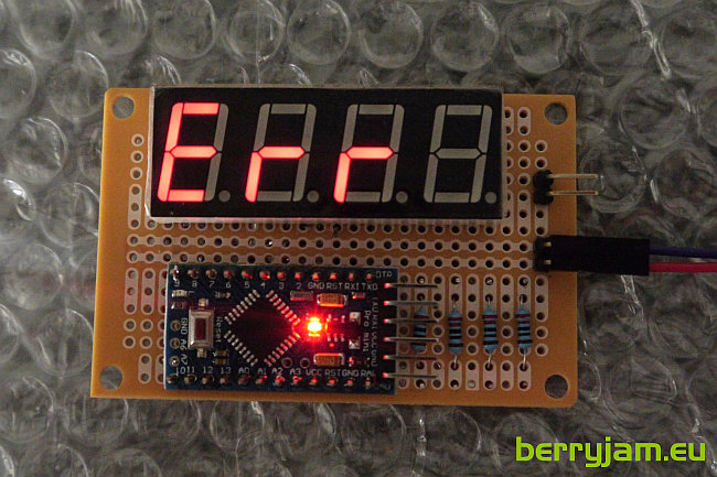
This Arduino Pro Mini has additional i2c control code inside (I have whole article about it) and acting like specialized LED driver IC, but is completely customizable and even cheaper (just 2.5$ if You buy it from ebay). Total cost of this i2c LED display is about 5$.
Short proof video:
Pingback: Multiplexing vs Charlieplexing | All Things Tech