First of all You won’t find here any information on high speed BLDC motor driving. For that purpose You need to know rotor’s position, so You have to measure back-EMF or use Hall sensors (not needed here).
For basic info about driving BLDC motors here is best “classic” articles on internets:
Driving a three-phase brushless DC motor with Arduino – Part 1. Theory
Driving a three-phase brushless DC motor with Arduino – Part 2. Circuit and Software
http://www.instructables.com/id/BLDC-Motor-Control-with-Arduino-salvaged-HD-motor/
I used specialized triple half bridge IC L6234 (~ 8$). You can make the same spending less money (but more time) with MOSFET transistors or other IC.
But be careful, I found a lot of cases in various forums, where people burned their Arduinos or L6234 chips.

ATTENTION
If You connect L6234 INputs directly to Arduino and OUTputs to low impedance motor – current from Arduino pins will be driven directly through L6234 to the windings and to the ground (without external Vs power applied to L6234). This makes very good chance to burn Your lovely microprocessor.
Also in application note, one sentence is worth to mention – “To avoid overload of the logic INPUTS and ENABLES, voltage should be applied to Vs prior to the logic signal inputs.”
I also very recommend to study (or/and purchase) this open hardware driver board based on L6234 BLDC Motor Driver by Michael Anton. It has input protecting resistors, zeners, power supply/filtering components and even back-EMF sensing circuit with amplifier (not used here).
L6234 datasheet is surprisingly useless. Go straight to Application Note AN1088 instead.
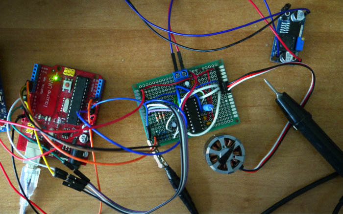
My setup of Arduino and DIY driver-board:

I added current limiting resistors (1kΩ) to all INputs and ENable pins, a bunch of capacitors recommended in application note and current sensing shunt resistor 0.6Ω (big blue one).
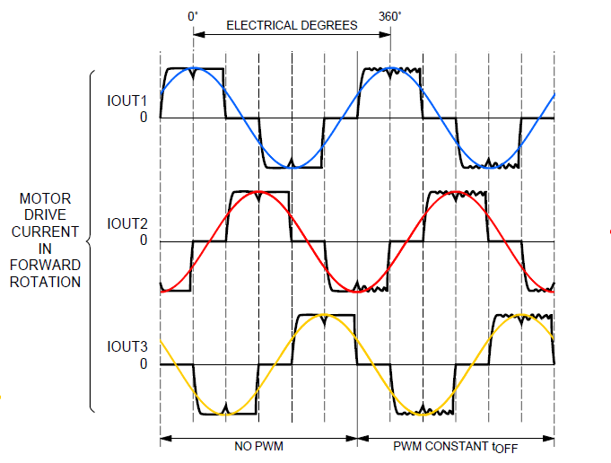
There is main illustration, for basic BLDC driving using 6 step sequence(rectangular current):

It works very well on high speeds. But on slow RPM’s You will have choppy steps. So we need to smooth out driving current to sine waves:

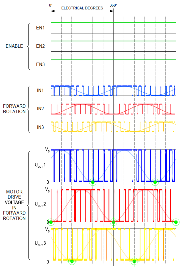
To achieve this, You simply set ENable pins to HIGH (as except few zero moments, voltage is continously changing). And feed the sine-wave modulated PWM (SPWM) to INput pins:

I didn’t tried to force Arduino to make sine calculations. Lookup tables was used instead. Here is a link to OpenOffice spreadsheet:
 BLDC_SPWM_Lookup_tables
You can generate traditional sine waves (SPWM) and Space-Vector PWMs (SVPWM). Try both and decide which to choose for Yourself.
And here is actual Arduino code, fused from different sources:
//
// Slow and precise BLDC motor driver using SPWM and SVPWM modulation
// Part of code used from http://elabz.com/
// (c) 2015 Ignas Gramba www.berryjam.eu
//


const int EN1 = 5;
const int EN2 = 6;
const int EN3 = 7;

const int IN1 = 9;
const int IN2 = 10;
const int IN3 = 11;


// SPWM (Sine Wave)
//const int pwmSin[] = {127, 138, 149, 160, 170, 181, 191, 200, 209, 217, 224, 231, 237, 242, 246, 250, 252, 254, 254, 254, 252, 250, 246, 242, 237, 231, 224, 217, 209, 200, 191, 181, 170, 160, 149, 138, 127, 116, 105, 94, 84, 73, 64, 54, 45, 37, 30, 23, 17, 12, 8, 4, 2, 0, 0, 0, 2, 4, 8, 12, 17, 23, 30, 37, 45, 54, 64, 73, 84, 94, 105, 116 };


/// SVPWM (Space Vector Wave)
//const int pwmSin[] = {128, 147, 166, 185, 203, 221, 238, 243, 248, 251, 253, 255, 255, 255, 253, 251, 248, 243, 238, 243, 248, 251, 253, 255, 255, 255, 253, 251, 248, 243, 238, 221, 203, 185, 166, 147, 128, 109, 90, 71, 53, 35, 18, 13, 8, 5, 3, 1, 1, 1, 3, 5, 8, 13, 18, 13, 8, 5, 3, 1, 1, 1, 3, 5, 8, 13, 18, 35, 53, 71, 90, 109};
const int pwmSin[] = {128, 132, 136, 140, 143, 147, 151, 155, 159, 162, 166, 170, 174, 178, 181, 185, 189, 192, 196, 200, 203, 207, 211, 214, 218, 221, 225, 228, 232, 235, 238, 239, 240, 241, 242, 243, 244, 245, 246, 247, 248, 248, 249, 250, 250, 251, 252, 252, 253, 253, 253, 254, 254, 254, 255, 255, 255, 255, 255, 255, 255, 255, 255, 255, 255, 255, 255, 254, 254, 254, 253, 253, 253, 252, 252, 251, 250, 250, 249, 248, 248, 247, 246, 245, 244, 243, 242, 241, 240, 239, 238, 239, 240, 241, 242, 243, 244, 245, 246, 247, 248, 248, 249, 250, 250, 251, 252, 252, 253, 253, 253, 254, 254, 254, 255, 255, 255, 255, 255, 255, 255, 255, 255, 255, 255, 255, 255, 254, 254, 254, 253, 253, 253, 252, 252, 251, 250, 250, 249, 248, 248, 247, 246, 245, 244, 243, 242, 241, 240, 239, 238, 235, 232, 228, 225, 221, 218, 214, 211, 207, 203, 200, 196, 192, 189, 185, 181, 178, 174, 170, 166, 162, 159, 155, 151, 147, 143, 140, 136, 132, 128, 124, 120, 116, 113, 109, 105, 101, 97, 94, 90, 86, 82, 78, 75, 71, 67, 64, 60, 56, 53, 49, 45, 42, 38, 35, 31, 28, 24, 21, 18, 17, 16, 15, 14, 13, 12, 11, 10, 9, 8, 8, 7, 6, 6, 5, 4, 4, 3, 3, 3, 2, 2, 2, 1, 1, 1, 1, 1, 1, 1, 1, 1, 1, 1, 1, 1, 2, 2, 2, 3, 3, 3, 4, 4, 5, 6, 6, 7, 8, 8, 9, 10, 11, 12, 13, 14, 15, 16, 17, 18, 17, 16, 15, 14, 13, 12, 11, 10, 9, 8, 8, 7, 6, 6, 5, 4, 4, 3, 3, 3, 2, 2, 2, 1, 1, 1, 1, 1, 1, 1, 1, 1, 1, 1, 1, 1, 2, 2, 2, 3, 3, 3, 4, 4, 5, 6, 6, 7, 8, 8, 9, 10, 11, 12, 13, 14, 15, 16, 17, 18, 21, 24, 28, 31, 35, 38, 42, 45, 49, 53, 56, 60, 64, 67, 71, 75, 78, 82, 86, 90, 94, 97, 101, 105, 109, 113, 116, 120, 124};

int currentStepA;
int currentStepB;
int currentStepC;
int sineArraySize;
int increment = 0;
boolean direct = 1; // direction true=forward, false=backward

//////////////////////////////////////////////////////////////////////////////

void setup() {

  setPwmFrequency(IN1); // Increase PWM frequency to 32 kHz  (make unaudible)
  setPwmFrequency(IN2);
  setPwmFrequency(IN3);

  pinMode(IN1, OUTPUT);
  pinMode(IN2, OUTPUT);
  pinMode(IN3, OUTPUT);

  pinMode(EN1, OUTPUT);
  pinMode(EN2, OUTPUT);
  pinMode(EN3, OUTPUT);


  digitalWrite(EN1, HIGH);
  digitalWrite(EN2, HIGH);
  digitalWrite(EN3, HIGH);


  sineArraySize = sizeof(pwmSin)/sizeof(int); // Find lookup table size
  int phaseShift = sineArraySize / 3;         // Find phase shift and initial A, B C phase values
  currentStepA = 0;
  currentStepB = currentStepA + phaseShift;
  currentStepC = currentStepB + phaseShift;

  sineArraySize--; // Convert from array Size to last PWM array number
}

//////////////////////////////////////////////////////////////////////////////

void loop() {

  analogWrite(IN1, pwmSin[currentStepA]);
  analogWrite(IN2, pwmSin[currentStepB]);
  analogWrite(IN3, pwmSin[currentStepC]);

  if (direct==true) increment = 1;
  else increment = -1;

  currentStepA = currentStepA + increment;
  currentStepB = currentStepB + increment;
  currentStepC = currentStepC + increment;

  //Check for lookup table overflow and return to opposite end if necessary
  if(currentStepA > sineArraySize)  currentStepA = 0;
  if(currentStepA < 0)  currentStepA = sineArraySize;

  if(currentStepB > sineArraySize)  currentStepB = 0;
  if(currentStepB < 0)  currentStepB = sineArraySize;

  if(currentStepC > sineArraySize)  currentStepC = 0;
  if(currentStepC < 0) currentStepC = sineArraySize;

  /// Control speed by this delay
  delay(10);

}


void setPwmFrequency(int pin) {
  if(pin == 5 || pin == 6 || pin == 9 || pin == 10) {
    if(pin == 5 || pin == 6) {
      TCCR0B = TCCR0B & 0b11111000 | 0x01;
    } else {
      TCCR1B = TCCR1B & 0b11111000 | 0x01;
    }
  }
  else if(pin == 3 || pin == 11) {
    TCCR2B = TCCR2B & 0b11111000 | 0x01;
  }
}
After compilation You will have info that there are still plenty of memory. Even after heavy 360 values sine array.
Sketch uses 2,418 bytes (7%) of program storage space. Maximum is 32,256 bytes.
Global variables use 741 bytes (36%) of dynamic memory, leaving 1,307 bytes for local variables. Maximum is 2,048 bytes.
So, there are 360 “steps” in one electrical revolution, and tested motor had 6 electrical revolutions, per one mechanical. This means 360×6 = 2160 “steps” per mechanical revolution or 0,16(7) degree of precision. If not enough, You can make even 3x more precise lookup table.
Here is some video illustrating results (You have to be very patient to notice movement on last one! )
SVPWM modulation is used in this video. Pot interactively changes delay(); value.

Pingback: Driving A Brushless DC Motor Sloooooooowly | Ad Pub
Pingback: Driving A Brushless DC Motor Sloooooooowly - zeax blog (ze-ax.com)
Pingback: Driving A Brushless DC Motor Sloooooooowly | Hack The Planet
Pingback: Driving A Brushless DC Motor Sloooooooowly | MyWebspace
Pingback: Spining BLDC motors at super Slow speeds with Arduino and L6234 - Arduino collector blog
Pingback: Hard Drive Wall Clock (first concepts) | modified.systems
Pingback: Spining BLDC motors at super Slow speeds with Arduino and L6234 -Use Arduino for Projects
Pingback: [Tuto] Pilotage de moteur triphasé à faible vitesse
Pingback: Sensorless BLDC Motor Control Based on Arduino UNO - Electronics DNA
Pingback: Simple VFD 3 Phase Induction Motor SinePWM using Arduino UNO - Electronics DNA
Pingback: Preliminary experiment with SPWM 3 Phase Induction Motor - Electronics DNA
Pingback: Spining BLDC(Gimbal) motors at super slooooooow speeds with Arduino and L6234 -
Pingback: Arduino Speed Control 3 Phase Induction Motor by TM-35 (V.1) - ElectronicsDNA
Pingback: Arduino Speed Control 3 Phase Induction Motor by TM-35 (V.2) - ElectronicsDNA